FanPico User Manual
FanPico is a generic programmable (PWM) fan controller. Altough it was initially created to be used inside a PC, it can be used for other purposes and does not necessarily require any fan PWM signals (from motherboard). It could be easily programmed to control fan speeds based on temperatures measured by one or more temperature sensors.

| Connector | Description | Notes |
|---|---|---|
| MB FAN1 | Fan Signal Input from motherboard | Can be used to power FAN1 and/or FAN5 (and FanPico itself) |
| MB FAN2 | Fan Signal Input from motherboard | Can be used to power FAN2 and/or FAN6 |
| MB FAN3 | Fan Signal Input from motherboard | Can be used to power FAN3 and/or FAN7 |
| MB FAN4 | Fan Signal Input from motherboard | Can be used to power FAN4 and/or FAN8 |
| AUX POWER | Auxiliary Power Input | Can be used to power any of the FAN outputs (and FanPico itself) |
| SENSOR1 | Remote Temperature Probe | K-type probe 10k or 100k nominal resistance (JST 2.5mm connector) |
| SENSOR2 | Remote Temperature Probe | K-type probe 10k or 100k nominal resistance (JST 2.5mm connector) |
| FAN1 | Fan Output | |
| FAN2 | Fan Output | |
| FAN3 | Fan Output | |
| FAN4 | Fan Output | |
| FAN5 | Fan Output | |
| FAN6 | Fan Output | |
| FAN7 | Fan Output | |
| FAN8 | Fan Output | |
| Serial (TTL) | Serial Console | This is for 3.3V TTL level serial connector (not RS-232!) |
| SPI | I2C / SPI | Pins shared between SPI and I2C bud. Current firmware does not support SPI, but this could be used to connect I2C bus devices |
| USB | RPi Pico USB | USB Serial Console for programming and monitoring. |
| Jumper | Name | Description |
|---|---|---|
| JP1 | Main Power | Main Power Input selection(AUX POWER connector / MB FAN1 connector) |
| JP2 | FAN1 Power | FAN1 Power Source selection (MB FAN1 connector / AUX POWER connector) |
| JP3 | FAN2 Power | FAN2 Power Source selection (MB FAN2 connector / AUX POWER connector) |
| JP5 | FAN3 Power | FAN3 Power Source selection (MB FAN3 connector / AUX POWER connector) |
| JP4 | FAN4 Power | FAN4 Power Source selection (MB FAN4 connector / AUX POWER connector) |
| JP6 | FAN5 Power | FAN5 Power Source selection (MB FAN1 connector / AUX POWER connector) |
| JP7 | FAN6 Power | FAN6 Power Source selection (MB FAN2 connector / AUX POWER connector) |
| JP8 | FAN7 Power | FAN7 Power Source selection (MB FAN3 connector / AUX POWER connector) |
| JP9 | FAN8 Power | FAN8 Power Source selection (MB FAN4 connector / AUX POWER connector) |
| JP10 | SENSOR1 Type | Select between 10k ohm and 100k ohm NTC thermistor. |
| JP11 | SENSOR2 Type | Select between 10k ohm and 100k ohm NTC thermistor. |
| LED | Name | Description |
|---|---|---|
| D2 | 12V (AUX) | Indicator of 12V power input from AUX connector. |
| D4 | 5V | Indicator for internal 5V power rail. |
| D5 | 3.3V | Indicator for (Pico) 3.3V power. |
| D6 | USB Power | Indicator for USB 5V power input. |
| D7 | MB FAN1 | Indicator for 12V power input from MB FAN1 |
| D11 | MB FAN2 | Indicator for 12V power input from MB FAN2 |
| D19 | MB FAN3 | Indicator for 12V power input from MB FAN3 |
| D15 | MB FAN4 | Indicator for 12V power input from MB FAN4 |
| D8 | FAN1 | Indicator for 12V power output on FAN1 |
| D12 | FAN2 | Indicator for 12V power output on FAN2 |
| D20 | FAN3 | Indicator for 12V power output on FAN3 |
| D16 | FAN4 | Indicator for 12V power output on FAN4 |
| D23 | FAN5 | Indicator for 12V power output on FAN5 |
| D26 | FAN6 | Indicator for 12V power output on FAN6 |
| D29 | FAN7 | Indicator for 12V power output on FAN7 |
| D32 | FAN8 | Indicator for 12V power output on FAN8 |
| Test Point | Name | Description |
|---|---|---|
| TP1 | 12V AUX | 12V Input from AUX |
| TP2 | 5V AUX | 5V Input from AUX (Not used) |
| TP3 | 5V | Internal 5V Power rail |
| TP4 | 3.3V | Internal (Pico generated) 3.3V Power rail |
| TP5 | USB Power | USB Power Input (5V) |
| TP6 | MB FAN1 | MB FAN1 12V input |
| TP7 | MB FAN2 | MB FAN2 12V input |
| TP8 | MB FAN3 | MB FAN3 12V input |
| TP9 | MB FAN4 | MB FAN4 12V input |
FanPico (unit itself) can be powered from the first motherboard fan input (MB FAN1) or alternatively from the Auxiliary ("Floppy") power connector (AUX POWER).
Use jumper JP1 (Main Power) to select the power source. Make sure to check that "5V" LED (D4) is lit, indicating that JP1 is set correctly.
NOTE! If powering FanPico only from AUX connector, make sure this connector is set to AUX position, otherwise board doesn't have 5V power and fan speed control will not work.
FanPico typically consumes under 100mA from 12V Input. Power consumption can wary significantly depending on if using Pico or Pico W (WiFi can use significant amount of power) and if using OLED module or not.
In power calculations it is probably best budget 200mA for the FanPico itself.
AUX POWER input is meant to draw up to 3A (there is PolyFuse that will start limiting if usage goes over).
MB FAN inputs should not draw more than the corresponding motherboard output is rated for.
To be sure that all Fans will get enough power and not too much current is drawn from any of the inputs (AUX POWER or MB FAN inputs) it is good to calculate (maximum) power consumption for each input.
With modern motherboards (that generally provide at least 1A on each motherboard fan output) and modern fans (that typically rated around 0.3A at 12V) FanPico can be safely powered from just only motherboard outputs. But it is still good idea to make sure not too much strain is put on motherboard fan outputs.
Following "worksheet" could be used to determine that there is sufficient power available:
| Input | Input Max Current | Output 1 | Output 1 Current | Output 2 | Output 2 Current | FanPico Curent | Output Max Current |
|---|---|---|---|---|---|---|---|
| MB FAN1 | FAN1 | FAN5 | 0.2A | ||||
| MB FAN2 | FAN2 | FAN6 | N/A | ||||
| MB FAN3 | FAN3 | FAN7 | N/A | ||||
| MB FAN4 | FAN4 | FAN8 | N/A |
- First fill in the "Input Max Current" column based on the motherboard documentation
- Then fill in the fan max current for each FAN (that is not set to be powered from "AUX")
- Finally fill in 0.2A for "FanPico Current" on first row, if powering FanPico from MF FAB1 connector.
- Calculate "Output Max Current" by adding up the "Output 1 Current", "Output 2 Current", and "Fan Pico Current"
- Finally, check that Output Max Current is never higher than the Input Max current.
If output max current is higher for some MB FAN input, then consider powering one of the FANs from AUX POWER or using lower power FAN, etc...
AUX POWER input has 3A fuse protecting it. So it is good idea to make sure that the planned fan configuration will not end up using more than that.
Following "worksheet" could be used to calculate power usage:
| Connector | Max Current | Notes |
|---|---|---|
| FAN1 | ||
| FAN2 | ||
| FAN3 | ||
| FAN4 | ||
| FAN5 | ||
| FAN6 | ||
| FAN7 | ||
| FAN8 | ||
| FanPico | Enter "0.2A" if powering FanPico from AUX POWER (JP1 set to "AUX") |
- Enter max current for each FAN connector that is configured to be powered from "AUX" (otherwise leave empty or enter zero)
- Calculate total current by adding up all the values on second column.
- Check that the result is less than 3A
If result is over the max current for AUX POWER connector, consider powering some of the fans from MB FAN inputs or using fans with lower power consumption.
Latest pre-compiled firmware image can be found here: Releases
Firmware can be installed via the built-in UF2 bootloader on the Raspberry Pi Pico or using the debug header with Picoprobe, etc...
Each release (zip file) contains multiple different firmware files. Make sure to select firmware for the board you're using and for the pico model ("pico_w" if using Pico W).
Firmware file names have format: fanpico-<board_model>-<pico_model>.uf2
fanpico-0804-pico.uf2
fanpico-0804-pico_w.uf2
fanpico-0804D-pico.uf2
fanpico-0804D-pico_w.uf2
Firmware upgrade steps:
- Connect Pico to a computer using Micro USB cable.
- Boot Pico into UF2 bootloader. This can be done in two ways:
- Press and hold
BOOTSELbutton and then press and releaseRESETbutton. - Issue command: SYS:UPGRADE
- Press and hold
- Copy firmware file to the USB mass storage device that appears.
- As soon as firmware copy is complete, Pico will reboot and run the fanpico firmware.
FanPico PCBs have 4 mounting holes that are grounded, so it's safe to mount it directly to a PC case using metal screws/mounts. But it is fine to use plastic mounts/screws if desired, as MBFAN connections or AUX POWER connection will connect the ground on FanPico to the computer ground.
When installing FanPico following connections are typically needed:
- MB FANs: One or more motherboard FAN outputs (4-pin PWM outputs) connected, to provide power and PWM signals to drive fans. NOTE, it is possible to use FanPico without using these connections if planning on controlling fans from temperature sensors or using a program/script to control fan speeds using the SCPI command set.
- AUX POWER: If there is not enough power provided by motherboard FAN connectors (outputs), this can be used to power Fans connected to FanPico.
- USB: This is typically connected to motherboard USB 2.0 header for programming and monitoring purposes.
- FANs: One or more 4-prin PWM fans connected to the FAN ports.
This examples shows the process of setting up FanPico on a PC that has 5 case fans and 1 CPU fan. So that FanPico is controlling all the fans.

- Motherboard: ASUS Prime X570-Pro
- Using 4 PWM Fan outputs (all rated 1A each): "CPU_FAN", "CHA_FAN1", "CHA_FAN2", "CHA_FAN3"
- Using USB2.0 pin header for FanPico "console": "USB34"
- Fans
- Top Exhaust: 2 x Noctua NP-14s redux 1500 PWM (0.20A)
- Front Intake: 2 x Scythe KF1425FD12SR-P 1200 PWM (0.12A)
- Rear Exhaust: 1 x Scythe KF1425FD12SR-P 1200 PWM (0.12)
- CPU Cooler: Noctua NF-A15 1500 PWM (0.13A)
- FanPico 0804D (or 0804)
- Temperature Sensors: generic 10k Ohm NTC with JST 2.5mm connector (for measure temperature of air intake and exhaust)
- PWM extension cables (4-pin female to 4-pin male)
- PWM "motherboard" cables (4-pin female to 4-pin female)
- Motherboard USB 2.0 header to Micro USB cable (alternatively generic motherboard USB2.0 cable to USB-A and regular Micro-USB cable works)
- Motherboard standoffs (and some M3 lock nuts for securing them)
If using FanPico without a display (or using cable to relocate the display) it is often easies to install in on the "back side" of typical PC case. But if using it with nice OLED module it is nice to have unit visible through transparent side panel.
On our example system there is plenty of "free" space beside the 5.25" drive bays. So drilling two 1/8" holes and installing brass motherboard standoffs (using M3 locknuts so they won't come loose):


Cabling can be tricky, since depending on FanPico mounting location and location of motherboard connectors, chassis fans, etc. usually means that large number of different cable lengths is needed.
Connecting motherboard FAN (outputs) to FanPico "MB FAB" inputs to provide power and fan PWM input signals (as well as tachometer output signals back to motherboard).
These connections require 4-pin Female to Female cables. These cables exist but can be hard to find. So one option is to build your own cables from scratch. If you're comfortable crimping your own connectors, easies is to cutoff the 4-pin male connector and replace it with 4-pin female connector.
Another alternative is to use two "extension" cables and cutoff the 4-pin male connectors, then solder the two cables together.
In this example we're running cables as follows:
| Motherboard Connector | FanPico Connector |
|---|---|
| CPU_FAN | MBFAN1 |
| CHA_FAN1 | MBFAN2 |
| CHA_FAN2 | MBFAN3 |
| CHA_FAN3 | MBFAN4 |
Connect chassis fans to "FAN" connectors on Fan Pico.
This is straightforward process, simply connect fans directly (if fan's own cable is long enough) or using extension cables as needed.
In this example we connect fans as follow (fans can be connected to any output):
| Fan Location | FanPico Connector |
|---|---|
| CPU Cooler | FAN1 |
| Rear (Exhaust) Fan | FAN2 |
| Front (Intake) #1 | FAN5 |
| Front (Intake) #2 | FAN6 |
| Top (Exhaust) #1 | FAN7 |
| Top (Exhaust) #2 | FAN8 |
Temperature sensors can be used to monitor temperature inside the PC.
In our example we decided to monitor intake air temperature and exhaust air temperature.
| Sensor Location | FanPico Connector |
|---|---|
| Behind front intake fan | SENSOR1 |
| Behind rear exhaust fan | SENSOR2 |


USB (Console) connection is meant to be connected on one of the motherboard USB 2.0 connectors so that it is easy to configure and monitor FanPico.

NOTE, if using USB port that is "always on", then FanPico can be used to monitor system temperatures even when system is off.
Now we get to the fun part. Configuring FanPico to control our fans the way we like.
First we need to get connected to the console. For this any terminal emulation program will do.
On Windows PuTTY is one good option. On Linux and MacOS "tio" is easy to use.
To validate that connection is working we can issue *IDN? SCPI command to request instrument to identify itself.
To use PuTTY to connect to FanPico console is rather easy. Just need to know which COM port FanPico got assigned to and set baudrate to 115200.
In this example FanPico got assigned "COM3" so we select COM3:

Additionally you may want to enable local echo and editing in under Terminal settings so you can see what when you type commands:

Next use "Connect" to open terminal emulator.
Check that connection to FanPico works by sending command *IDN?:

With tio we can specify speed (baud rate) from command line along with local echo.
On Linux RaspberryPi Pico usually gets device name like /dev/ttyACM0, while on MacOS it gets name like /dev/cu.usbmodem83101.
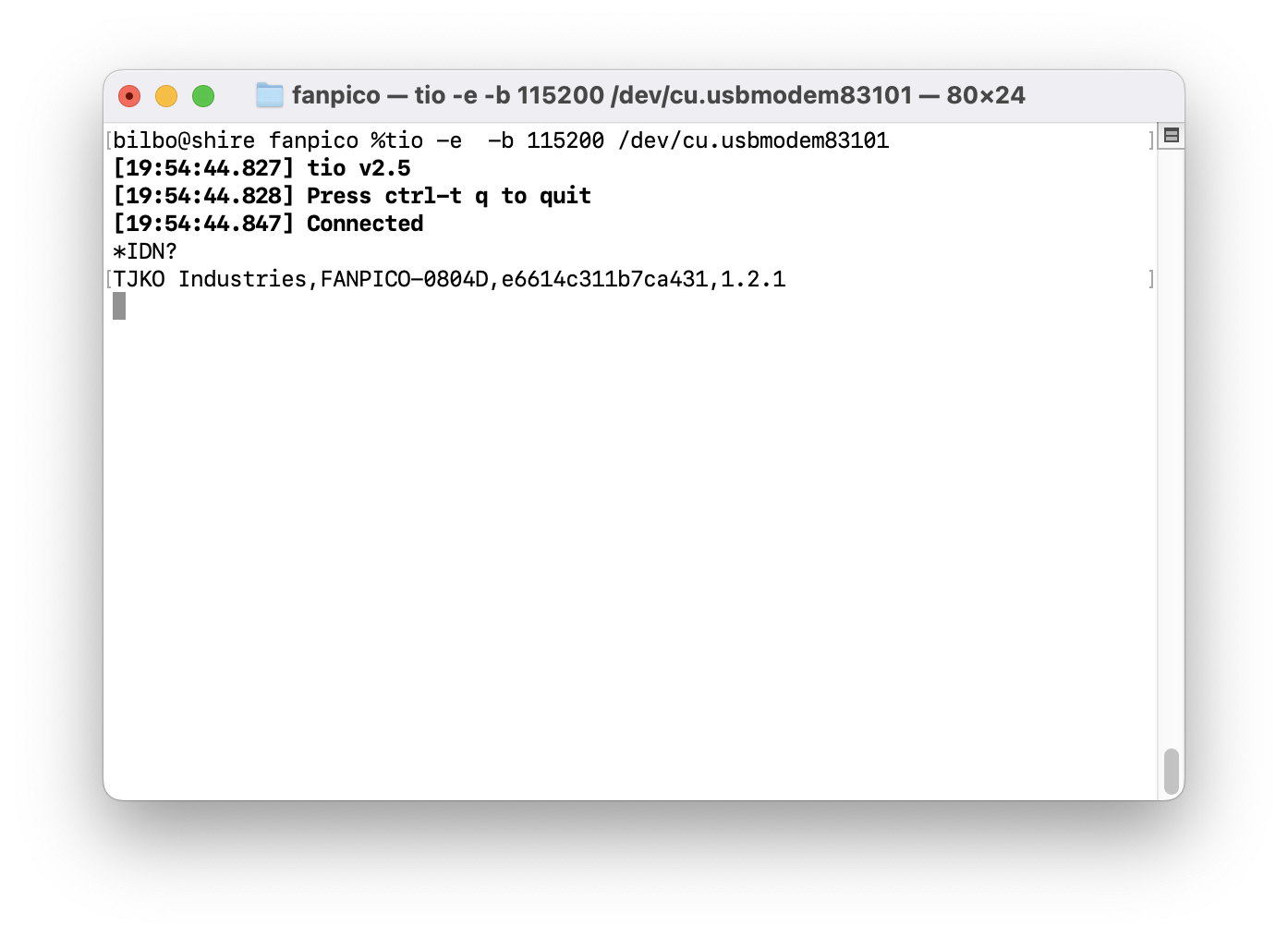
After we have working connection to the device, we can start configuring it using.
See Command Reference for full list of available commands.
First step should be to clear existing configuration (if any) from the device. So we start from known default state.
This can be done by issuing CONF:DEL command and then rebooting the unit by using *RST command:
CONF:DEL
*RST
Next we'll want to name our inputs and outputs.
In our example we had connected MBFAN inputs as follows:
| Motherboard Connector | FanPico Connector |
|---|---|
| CPU_FAN | MBFAN1 |
| CHA_FAN1 | MBFAN2 |
| CHA_FAN2 | MBFAN3 |
| CHA_FAN3 | MBFAN4 |
Now we can use CONF:MBFANx:NAME command to set names for these inputs:
CONF:MBFAN1:NAME CPU Fan
CONF:MBFAN2:NAME Chassis Fan 1
CONF:MBFAN3:NAME Chassis Fan 2
CONF:MBFAN4:NAME Chassis Fan 3
In our example we had connected FAN outputs as follows:
| Fan Location | FanPico Connector |
|---|---|
| CPU Cooler | FAN1 |
| Rear (Exhaust) Fan | FAN2 |
| Front (Intake) #1 | FAN5 |
| Front (Intake) #2 | FAN6 |
| Top (Exhaust) #1 | FAN7 |
| Top (Exhaust) #2 | FAN8 |
Now we can use CONF:FANx:NAME command to set names for these (Fan) outputs:
CONF:FAN1:NAME CPU Fan
CONF:FAN2:NAME Rear Exhaust
CONF:FAN3:NAME unused
CONF:FAN4:NAME unused
CONF:FAN5:NAME Front Intake 1
CONF:FAN6:NAME Front Intake 2
CONF:FAN7:NAME Top Exhaust 1
CONF:FAN8:NAME Top Exhaust 2
Temperature sensors were connected as follows:
| Sensor Location | FanPico Connector |
|---|---|
| Behind front intake fan | SENSOR1 |
| Behind rear exhaust fan | SENSOR2 |
Now we can name sensors using CONF:SENSORx:NAME commands.
CONF:SENSOR1:NAME Intake Air
CONF:SENSOR2:NAME Exhaust Air
CONF:SENSOR3:NAME RPi Pico
Now is good time to save configuration using CONF:SAVE before moving to next step:
CONF:SAVE
Next we want to decide tachometer (fan RPM) feedback we'll want to provide back to motherboard.
Default configuration is that FAN1 to FAN4 provide (unmodfied) tachometer signal to MBFAN1 to MBFAN4 ports. Since we don't have anything connected to FAN3 and FAN4 we'll want to at least adjust these, otherwise moterhoard would register "0 rpm" fan speed on these connectors.
| Connector | Tachometer Source (RPM) |
|---|---|
| MBFAN1 | FAN1 (CPU Cooler) |
| MBFAN2 | FAN2 (Rear Exhaust) |
| MBFAN3 | FAN5 (Front Intake 1) |
| MBFAN4 | FAN7 (Top Exhaust 1) |
Above can be configured using command CONF:MBFANx:SOURCE as follows (configuring MBFAN1 and MBFAN2 is strictly not necessary since as setting for these is the default one):
CONF:MBFAN1:SOURCE FAN,1
CONF:MBFAN2:SOURCE FAN,2
CONF:MBFAN3:SOURCE FAN,5
CONF:MBFAN4:SOURCE FAN,7
Tip: it is also possible to configure static (fixed) tachometer signal, in case using passive cooling, to avoid error from Motherboard BIOS during boot by using "FIXED" source and specifying desired RPM speed as parameter. For example:
CONF:MBFAN3:SOURCE FIXED, 500
(above would always provide fixed "500 rpm" signal back to motherboard on MBFAN3 connector)
Next we'll want to configure which motherboard speed (PWM) signals control which fan.
Default configuration is for MBFAN1 through MBFAN4 control FAN1 through FAN4 (and FAN5 to FAN8 respectively for MBFAN2 controls FAN2 and FAN6).
In our example we'll want to fans be controlled as follows:
| MBFAN Connector | FAN Connector |
|---|---|
| MBFAN1 (CPU_FAN) | FAN1 (CPU Cooler) |
| MBFAN2 (CHA_FAN1) | FAN2 (Rear Exhaust) |
| MBFAN3 (CHA_FAN2) | FAN5 and FAN6 (Front Intake) |
| MBFAN4 (CHA_FAN3) | FAN7 and FAN8 (Top Exhaust) |
This can be configured using CONF:FANx:SOURCE command.
CONF:FAN1:SOURCE MBFAN,1
CONF:FAN2:SOURCE MBFAN,2
CONF:FAN5:SOURCE MBFAN,3
CONF:FAN6:SOURCE MBFAN,3
CONF:FAN7:SOURCE MBFAN,4
CONF:FAN8:SOURCE MBFAN,4
Tip: it is possible to configure 4 different types of "sources" for Fan speed (PWM) signal:
- Motherboard PWM signal (MBFAN connector)
- Speed of another FAN (FAN connector)
- Temperature (sensor) (SENSOR connector)
- Set fixed fan speed at desired PWM value (0 to 100%).
After basic configuration is done. We'll observe the system for a while and notice that since we have 3 exhaust fans and 2 intake fans there is imbalance on the airflow. Additionally, top exhaust fans have higher maximum RPM rating than the other case fans, so they run at faster RPMs with given PWM signal (duty cycle).
Also, we notice that our motherboard simply feeds exact same speed (PWM duty cycle) signal out to all FAN connectors (case fans seem to follow 1:1 the CPU fan that appears to be tied to CPU temperature).
Current configuration seems to result in negative air pressure inside the case causing, some air being 'sucked' in from the open ventilation holes. We'll want balanced (or slightly positive) air pressure inside the case. So that most of the air will come in through the front air intake (and through the dust filter), and most of the air will be leaving through the exhaust fans.
We can fine tune fan speeds by adjusting coefficient for the output PWM signal (duty cycle) on each FAN connector using CONF:FANx:PWMC commands.
NOTE! In this case all case fans receive same speed (PWM duty cycle) signal even when they're controlled by different motherboard connectors, since our motherboard defaults to output same speed signal always on all connectors. So we can (for now) ignore the PWM source for each fan. But in general when balancing airflow across sets of fans it is good idea to have all these fans be controlled by same speed source.
After bit of experimenting we'll find that slowing down the top fans by 35% and the read exhaust fan 20% (and leaving front intake fans at default setting (100%) we'll achieve slightly positive air pressure inside the case.
So we'll set the rear fan coefficient to 0.8 (80%) and top fans to 0.65 (65%):
CONF:FAN2:PWMC 0.8
CONF:FAN7:PWMC 0.65
CONF:FAN8:PWMC 0.65
Since we have temperature sensor behind the rear exhaust fan, we'll have pretty good idea how "hot" it is inside the case (near CPU anyways). To make system hopefully more quiet and reduce annoying 'erratic' behaviour of case fans when they're linked to CPU fan speed, we'll want to use temperature as source for case fan speeds.
To do this we need to set our case fans to follow the temperature sensor (SENSOR2 in our case):
CONF:FAN2:SOURCE SENSOR,2
CONF:FAN5:SOURCE SENSOR,2
CONF:FAN6:SOURCE SENSOR,2
CONF:FAN7:SOURCE SENSOR,2
CONF:FAN8:SOURCE SENSOR,2
Next we'll want to define "curve" to map temperature to fan "speed" (PWM duty cycle). This can be done using command CONF:SENSORx:TEMPMAP.
Default temperature to PWM map is the following:
| x (Temperature in C) | y (Fan Duty Cycle in %) |
|---|---|
| 20 | 0 |
| 50 | 100 |
In our case we'll want to use slightly different mapping:
| x (Temperature in C) | y (Fan Duty Cycle in %) |
|---|---|
| 20 | 0 |
| 25 | 20 |
| 40 | 100 |
Here our fans get 0% signal (depending on fan manufacture this means fan is stopped or it runs at its minimum speed) until temperature raises above 20C. From 20C to 25C PWM signal ramps up to 20% and them from 25C to 40C it "quickly ramps up to 100% (full speed).
CONF:SENSOR2:TEMPMAP 20,0,25,20,40,100
Now all the case fans are temperature controlled, following the speed (PWM) mapping we created to set the fan speed based on the temperature reading from the temperature sensor measuring exhaust air temperature.
If using Pico W in FanPico, then it is possible connect unit to network.
See FanPico Web Interface wiki page for details on configuring network.
If planning on using MQTT see: FanPico MQTT Client Configuration
After updating configuration it must be saved, otherwise any changes to configuration will be lost when unit is reset.
To save current (running) configuration into Pico flash memory use CONF:SAVE:
CONF:SAVE