External Stepper Drivers
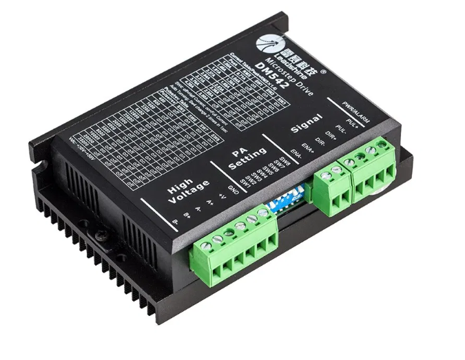
External stepper motor drivers are typically used when you want more power than the the small plug-in drivers can supply. You can also get advanced features like closed loop stepper and servo motors.
As long as they accept step and direction signals, you can probably use them. They usually have an enable signal and some have a fault signal. Grbl_ESP32 currently supports the enable. We hope to support the fault signal on the next generation of Grbl_ESP32.
They typically have opto isolated inputs. These use LEDs and optical sensors to isolate the signal. Any noise or spikes on the motor side cannot jump that optical gap and hurt the controller side. These LEDs are generally sized for 5V. The ESP32 outputs 3.3V, so it generally cannot directly connect to the motor drivers. See below.
Note: Some people claim that there drivers work fine at 3.3V. Be careful. It is hard to tell if the driver is happy all the time, or 99.9% of the time. Follow the published spec of the driver.
These isolating input features can add a little lag time on the speed of detecting the step, direction and enable signals. Grbl_ESP32 has several settings to compensate for this.
Many signals also have to be inverted. The isolation circuit flips the signal, so Grbl_ESP32 may need to adjust for that.
In the image below, you can see the pulse length requirements and required gaps between signals. The PUL (step signal) and DIR are inverted. The ENA is not, but you still might need to invert it because Grbl_ESP32 considers it a disable signal.

The following settings can be used to meet the signal requirements. You might add a little extra time when you first try it to be conservative. Keep in mind that very long pulse lengths, limits the top speed you can go.
Here are the settings. The "t" numbers from the image above are indicated.
- $Stepper/Pulse (t4) This is the duration in microseconds of the step pulse.
- $Stepper/StepInvert This inverts the step pulses
- $Stepper/Direction/Delay (t2) This is the delay before any step signal are sent after a direction signal changed.
- $Stepper/DirInvert This inverts the direction signal. This may need to be done for many reasons and could be different for each axis. It is a mask, so it is set like this $Stepper/DirInvert=XZ, by adding axes as required.
- $Stepper/Enable/Delay This is the gap between the enable and before the direction signal is set.
- $Stepper/EnableInvert (t1) This inverts the enable signal.
Example: Machine definition values
#define DEFAULT_STEP_ENABLE_DELAY        5 // how long after enable do we wait for
#define DEFAULT_STEP_PULSE_MICROSECONDS  4 // length of step pulse. Must be greater than I2S_OUT_USEC_PER_PULSE (4) with I2S
#define STEP_PULSE_DELAY                 6 // gap between enable and dir changes before step

#define DEFAULT_STEPPING_INVERT_MASK     (bit(X_AXIS) | bit(Y_AXIS) | bit(Z_AXIS))
#define DEFAULT_DIRECTION_INVERT_MASK    (bit(X_AXIS) | bit(Y_AXIS) | bit(Z_AXIS))
#define DEFAULT_INVERT_ST_ENABLE         false
3.3V to 5V Level shifting
Some controllers will have this built in. The 6 Pack has a jumper option for 3.3V and 5V output option. You should use the 5V output.
Note: Do not mix external with Trinamic drivers when using 5V. They send signals back to the ESP32 and will damage it with 5V
The 5V must have enough current to light the LEDs. The current is generally less than 20mA, but that is more than some cheap level shifts can deliver. Some level shifters (like T.I. TXB type) use a pull up resistors for the 5V and this will not power an LED.
There are a couple of adapters available to help with this. These both send the signals to the existing connectors.
6 Pack Adapter. This is just re-routes the 5V signals to the terminal blocks. It also allows the option of common 5V or common ground.
Note: Be very careful when wiring. If you short the outputs you could permanently damage the controller.

StepStick Adapter. This adapter does level shifting and re-routes the signals to the motor connector. It would be used on controllers that don't have 5V signals. It can be used on 3.3V or 5V controllers.
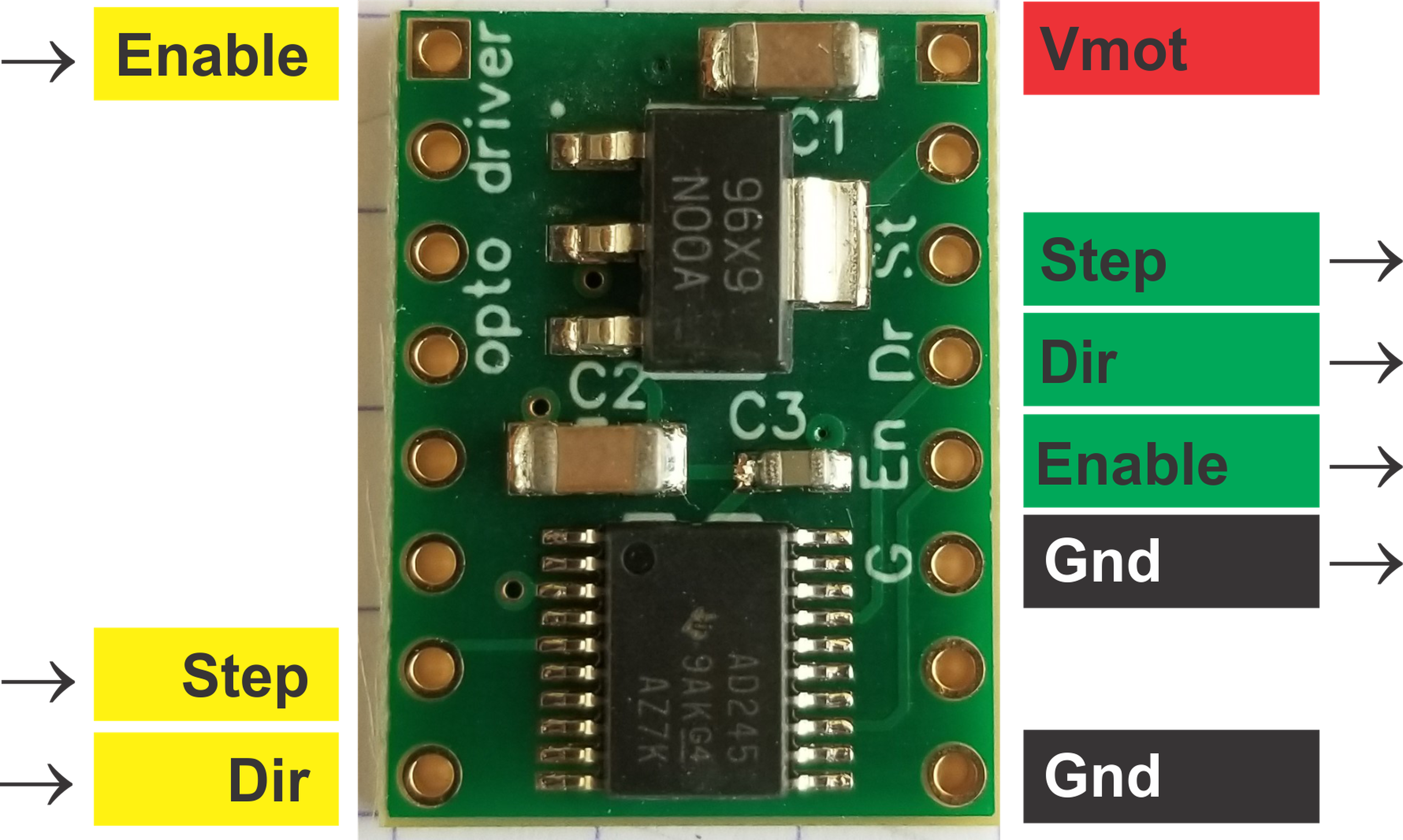
Each signal typically has a + and - connection. This allow you to wire them totally isolated from each other. The signals on the Grbl_ESP32 side generally will not be isolated from each other and share a common ground.
The easiest way to wire that is to connect all the minus sides together and connect that to ground on the controller. Wire the plus sides to the signals. This is shown below.

You could also wire the + sides together and connect that to +5V on the controller side. The minus sides would connect to the signals on the controller side. This is shown below.

- Erratic or missed steps This is often due to the step timing. These drivers often need longer pulse lengths to be reliably detected. Try lengthening the pulses. See settings section above.